 enEnglisch
Internal arc faults in pressurized air cables
Behavior of pressurized air cables during internal arc faults, pressure rise, and fault location in medium- and high-voltage networks
Operational reliability for modern power grids
Pressurized air cables are designed for the transmission of high power levels in medium-, high-, and extra-high-voltage networks. As with all electrical transmission systems, rare fault scenarios must also be taken into consideration.
One of the most severe events is a so-called internal arc fault — an arc occurring inside the system as a result of insulation failure. Although such events are rare, they place high demands on system design, pressure resistance, and fault diagnostics.
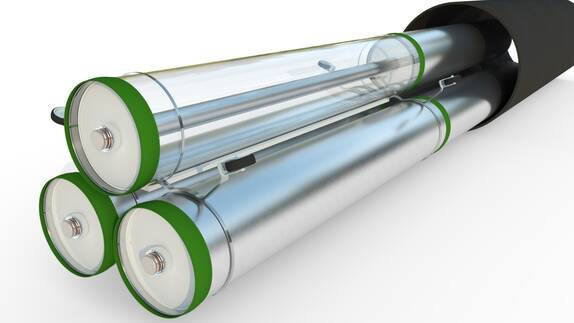
Pressurized air cables feature fully metallically enclosed conductors and defined gas compartments that are designed to ensure safe operation and controlled behavior in the event of a fault.
What are internal arc faults?
Internal arc faults are the result of an insulation failure within a pressurized air cable during operation.
They occur when the insulation between the conductor and the enclosure fails locally and an electric arc is initiated by the operating voltage. The arc carries the short-circuit current and, due to electromagnetic forces, travels at high speed along the inside of the pressurized air cable.
Typical short-circuit current levels in high-power applications are:
- 40 kA
- 50 kA
- 63 kA
with typical fault clearing times of 0.1 to 0.3 seconds.
Key facts at a glance
Energy and pressure during an internal arc fault
High energy release within a short period of time
During an internal arc fault, very large amounts of energy are released within just a few milliseconds. Part of this energy is transferred into heating and melting the affected conductors. Another portion heats the air inside the enclosure, resulting in a rise in pressure.
For typical short-circuit currents, the resulting energy levels are in the range of several megajoules.
Why air volume is critical
Larger volume results in lower pressure rise
The magnitude of the pressure rise depends directly on the available air volume within the enclosure. As a result, systems with larger internal volumes experience lower pressure increases for the same arc energy.
High-voltage products in particular benefit from their larger air volume and the correspondingly lower pressure peaks.
Gas compartment length and safety
Designed for short-circuit events
The pressure increase during an internal arc fault must remain below the burst limit of the enclosure.
For this reason, gas compartments are designed to provide sufficient safety margins even under high short-circuit current conditions.
Typical compartment lengths
Analysis shows that for high-voltage products, gas compartment lengths exceeding 15 meters are already sufficient to accommodate all common short-circuit specifications.
As a result, additional rupture discs are not required. Rupture discs would also represent a direct safety hazard, as they would burst during an internal arc fault and release hot gases into the surrounding area.
Fault location after an internal arc fault
Rapid identification of the fault location
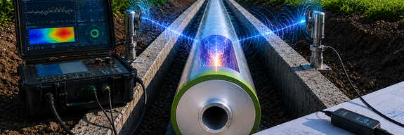
Following an internal arc fault, the affected section must be identified. Pressure monitoring for each gas compartment allows clear assignment of the fault to the affected gas compartment.
Within the gas compartment, the fault location can be determined even more precisely if two pressure sensors are installed at opposite ends of the compartment. The pressure pulse generated by the arc propagates in both directions. By evaluating the difference in arrival times at the sensors, the fault location can be calculated.
Benefits for maintenance and repair
- Faster fault analysis
- Reduced outage durations
- Targeted replacement of damaged components
- Improved grid availability
Comparison with gas-insulated switchgear
Rapid identification of the fault location
Gas-insulated switchgear typically uses small gas compartments for individual functions (e.g., circuit breakers, disconnectors, or feeder bays). As a result, internal arc faults generate significantly higher pressure peaks, making the use of rupture discs necessary.
Pressurized air cables, by contrast, utilize larger gas compartments. This reduces the pressure rise during an internal arc fault and eliminates the need for additional protective measures such as rupture discs.
Conclusion
Safety even in rare fault scenarios
Internal arc faults are among the rarest but most demanding events in electrical transmission systems. Pressurized air cables combine large-volume gas compartments, high mechanical strength, and integrated monitoring capabilities. This enables pressure rises to be controlled and fault locations to be identified efficiently. The robust system architecture supports safe operation even under demanding grid conditions.
Technical documents
Factsheets and technical documents
Frequently asked questions (FAQ)
What is an internal arc fault?
How does an internal arc fault occur?
What are the effects of an internal arc fault?
Why does pressure build up inside the system?
What is the role of gas compartment length?
Do pressurized air cables require rupture discs?
How is the fault location determined?
What advantages do pressurized air cables offer in the event of a fault?
Do you have questions about pressurized air cables?
Technical information, factsheets, and expert support for medium- and high-voltage projects — directly from the source.