 deDeutsch

Willkommen bei Hivoduct
Dem Unternehmen für nachhaltige Stromübertragung, massgeschneiderte Produkte & bahnbrechende Technologie
Druckluftkabel sind die nachhaltige Lösung für effiziente und zukunftsorientierte Stromübertragung. Wir bieten innovative, umweltfreundliche Technologien für eine bessere Energiezukunft. Profitieren Sie von massgeschneiderten Lösungen, die Effizienz, Sicherheit und Nachhaltigkeit vereinen.
Unsere Vision
Druckluftkabel sind der neue Standard für die elektrische Energieübertragung
News
Bleiben Sie auf dem Laufenden! Hier finden Sie die neuesten Entwicklungen und innovativen Projekte rund um unsere Unternehmung

 25. Mai 2025
Innovation braucht Systemkompetenz: Warum neue Wege im Stromnetzausbau entscheidend sind

Events
Werfen Sie einen Blick auf unsere bevorstehenden Veranstaltungen und sichern Sie sich Ihren Platz. Lassen Sie sich inspirieren und tauchen Sie ein in eine Welt voller Innovation und Erlebnisse. Wir freuen uns darauf, Sie persönlich begrüssen zu dürfen!
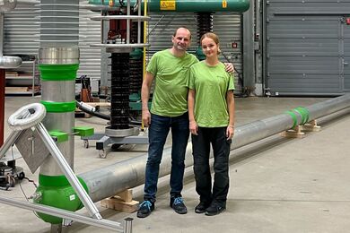
Möchten Sie vor Ort erleben, wie unsere hochwertigen Rohre produziert werden? Unsere Firmenbesichtigung bietet faszinierende Einblicke in die Prozesse, die hinter unseren erstklassigen Produkten stehen. Nutzen Sie die Gelegenheit, hinter die Kulissen zu schauen und unser Engagement für Qualität und Innovation hautnah mitzuerleben.
 16. September 2025 bis 18. September 2025, Power Transmission & Distribution Messe in Köln
Power Transmission & Distribution Messe
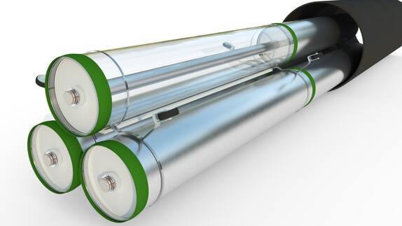
Hivoduct Druckluftkabel -Zukunftsweisende Technologie für eine nachhaltige Energieübertragung
Unsere innovative Druckluftkabel-Technologie setzt neue Massstäbe in der Energieinfrastruktur. Sie vereint höchste Effizienz, maximale Sicherheit und Umweltfreundlichkeit – perfekt für moderne, zukunftssichere Netzlösungen.
- Umweltfreundlich – Kein SF6, PFAS-frei, null Emissionen
- Maximale Effizienz – Geringe Verluste bei hohen Strömen, optimiert für höchste Leistungsfähigkeit
- Höchste Sicherheit – Geerdete, berührbare Gehäuse für zuverlässigen Schutz
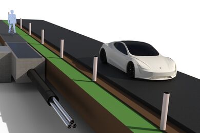
- Platzsparendes Design – Kompakte Verlegung ohne Muffen, reduzierte Baukosten
- Perfekt für Tunnel & unterirdische Anwendungen – Keine Brandlast, ideal für enge Räume
- Flexibel & wartungsfreundlich – Schraubenlose, demontierbare Flansche für eine einfache Wartung
Hivoduct – Die beste Wahl für zukunftssichere Energieübertragung!
Gestalten Sie
Ihre perfekte Leitung!
Nutzen Sie unseren benutzerfreundlichen Online-Konfigurator und erstellen Sie Ihre massgeschneiderte Leitung – schnell, einfach und individuell.
